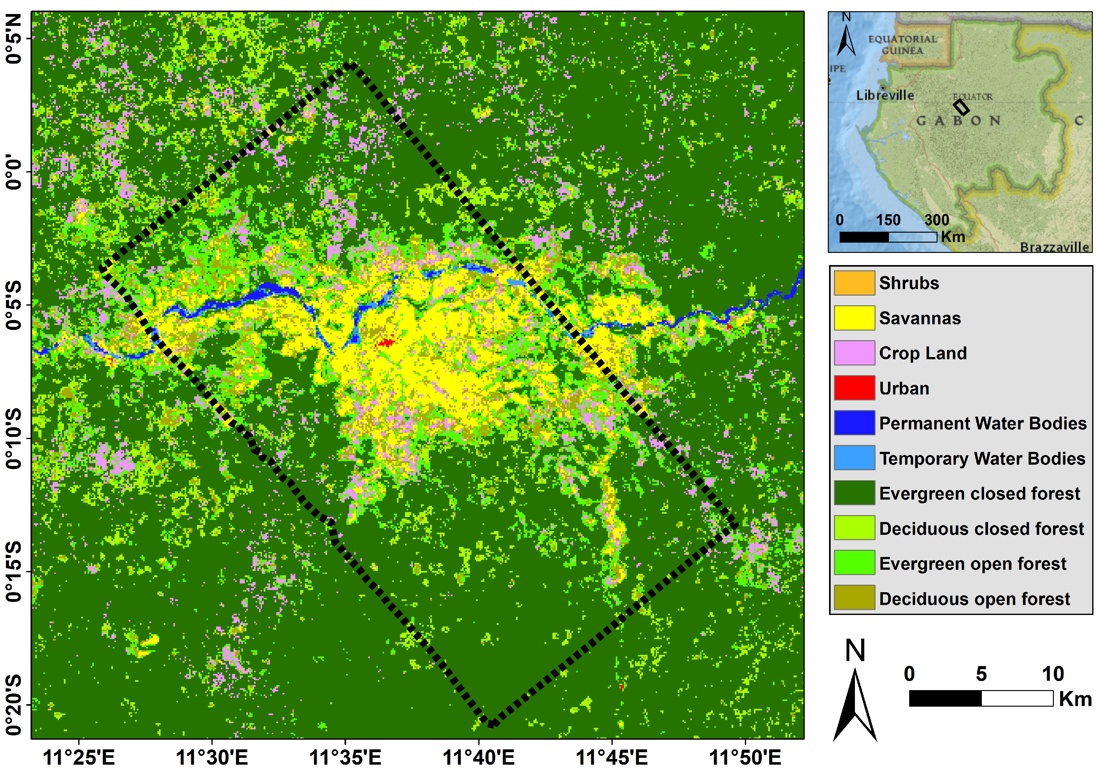
In the UAVSAR smart sensor concept Figure 14 , raw data from the radar observation are routed to the onboard processor via a high-speed serial interface. Transmitter output power variability. Forest fire and hurricane-induced damages on coastal landscapes and forests are considered the two most important disturbances of natural ecosystems and threats to human habitats. This calibration procedure is essentially a process of equalizing the phase and amplitude of each RF path to and from a particular antenna port. Shh, Shv, Svh, Svv. The data is in an equiangular-coordinate system in which each line and pixel increments in latitude and longitude. Data is projected to ground range and coregistered to the height file HGT. 
| Uploader: | Mozil |
| Date Added: | 10 March 2018 |
| File Size: | 44.81 Mb |
| Operating Systems: | Windows NT/2000/XP/2003/2003/7/8/10 MacOS 10/X |
| Downloads: | 50611 |
| Price: | Free* [*Free Regsitration Required] |
Autonomous detection is performed by an intelligent software routine designed to detect specific disturbances based on the results of science processing.
SnowEx17 GLISTIN-A and UAVSAR Interferometric Synthetic Aperture Radar, Version 1
UAVSAR characterizes an oil spill by detecting variations in the roughness of its surface and, for thick slicks, changes in the electrical conductivity of its surface layer. In the FPGA cata, range compression focuses the image in the cross track direction. This involves the development and mounting of the Ka-band front-end electronics to the backplane of a newly developed Ka-band antenna. The HGT file contains the elevation values used to project the slant-range data to the surface of the Earth.
UAVSAR - Airborne Sensors - eoPortal Directory
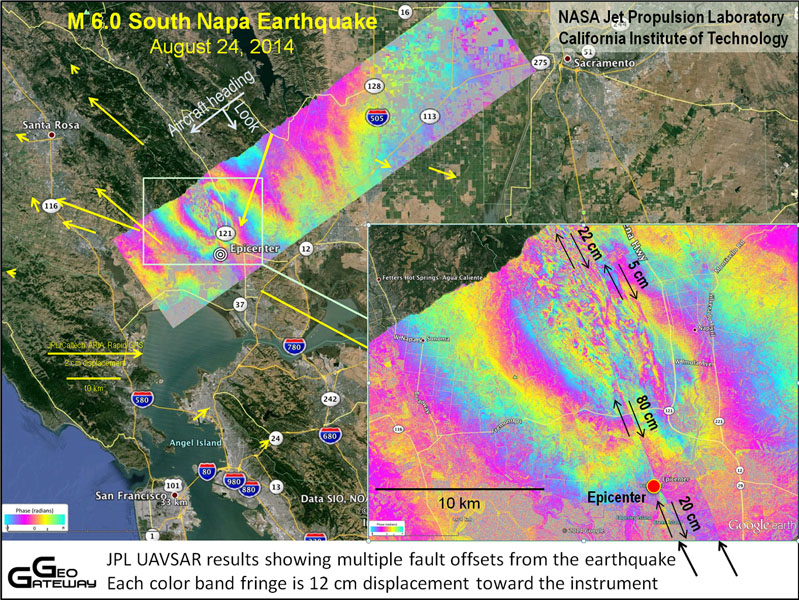
Transmit output power 50 ohm load. From such data, scientists will create 3-D maps for regions of interest Ref. Since NovemberJPL scientists have collected data gathered on a number of Gulfstream III flights over California's Dqta Andreas fault and other major California earthquake faults, a process that uabsar be repeated about every six months for the next several years.
Figure 12 is a block diagram of the phased antenna array which was designed, built and integrated at JPL. Phase stability 30 s at constant temperature. It killed two, injured hundreds and caused substantial damage. Mid-band gain variation nominal. The frequency of operation, approximately 1.

In the UAVSAR smart sensor concept Figure 14raw data from the radar observation are routed to the onboard processor via a high-speed serial interface. Other features supported by the antenna include elevation monopulse and pulse-to-pulse re-steering capabilities that will enable some novel modes of operation. It occurred along a geologically complex segment of the boundary between the North American and Pacific tectonic plates.
The quake, the region's largest in nearly years, was also felt in southern California and parts of Nevada and Arizona.
The sensor is undergoing a one-year development and test period to improve robustness and adta its ability to meet the science objectives. Architecture of the phased array image credit: Data product name and description Distribution disk files Returned data for supported format References. The ARC Automatic Radar Controller is the main control computer for the radar and controls all major functions of the radar during flight.
Legend to Figure 6: Within the caldera, the rising dome can be seen to the lower left. However, even with these simplifying attributes, calibration of this element active array as currently configured is both labor-intensive and time-consuming Ref.
UAVSAR Polarimetric
Four of the files are complex floating-point format, 8 bytes per pixel, uavswr to the scattering matrix. All of the processing levels and associated files may not be available for a particular data set nor is it required to download all of the available files.
Download daha PDF One data file. The antenna aperture comprises 48 patch antenna elements arranged as an array of 4 elements in elevation by 12 elements in azimuth.
The radar has been designed to minimize the number dqta interfaces with the aircraft for improved portability. The presum module resamples the pulses to a user-specified along track location and spacing to reduce the number of pulses to process in the along track azimuth direction while reducing the noise on each radar pulse.
The design features an AESA Active Electronically Scanned Array antenna which is electronically steered along-track to assure that the antenna beam can be directed independently, regardless of speed and wind direction. Receiver input 1 dB compression. The edge of Spirit Lake is at the upper center of the image and the tree line is visible in green.

Non-antenna port RF interface. This calibration procedure is essentially a process of equalizing the phase and amplitude of each RF path to and from a particular antenna port. The primary objective of the side-looking UAVSAR instrument is to accurately map crustal deformations associated with natural hazards, such as volcanoes and earthquakes.
For an observation flight, an experimenter may only select waypoints and the desired flight altitude - all other functions of platform control and navigation are being provided by the PPA.

No comments:
Post a Comment